

Team Octane Racing Electric
We are Team Octane Racing Electric, the Formula Student Team of COEP Technological University, Pune. We design and build Formula-style electric race cars from the ground up and compete in prestigious Formula FSAE events like Formula Bharat and Formula Student Germany. Supported by leading industries like BAJAJ Auto and Amphenol, we are moving beyond limits with battery management systems, autonomous system development, electronic control units and a custom motor controller.
The team was established in 2011 and started with Combustion Vehicles. After consistent top 5 performances in national events, the team decided to shift to Electric Vehicles in 2020.
Our recent achievements:
2018: First team in Asia to turbocharge a 'KTM390 engine' with a patented air intake.
2022: National Champions @ Formula Imperial
2024: 1st in Cost and Manufacturing, along with an overall Rank 4 at the Formula Bharat.
2025: The first Indian Team to implement a 588V Battery Pack, which powered a dual rear-wheel hub motor system, and was the sole Indian entry at Formula Student Germany 2025.
Secured 4th place in the MathWorks Modeling and Simulation Award at Formula Student Germany.
Our student engineers design every aspect of our car in-house and manufacture nearly 75% of it ourselves.
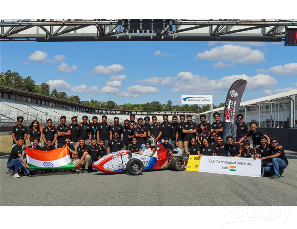
A glimpse from our trip to Formula Student Germany 2025, our first international event!
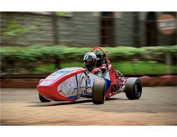
A picture from Blitz 1.0's testing.
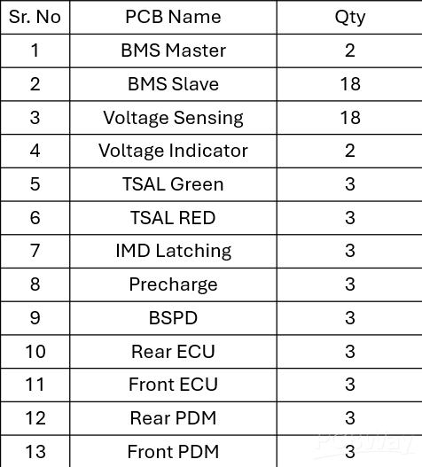
The following are the required PCBs -
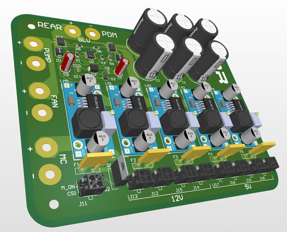
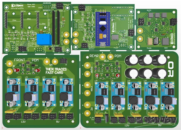
1. Power Distribution Module (PDM)
The Power Distribution Module (PDM) is responsible for distributing electrical power to the vehicle's electronic system while ensuring reliable circuit protection. It integrates various safety features such as overcurrent protection, overvoltage lookout (OVLO), undervoltage lookout (UVLO) and short to ground protection, thus safeguarding the vehicle's electronic components.
The PDM regulates the 12V supply from the battery so as to convert it into the necessary voltage levels. Various circuits, such as TSAL Red and Green, and IMD latching, etc, operate at various voltage levels such as 5V, 7V, 12V, and 24V (MCU). It houses thick traces and thermal vias so as to ensure maximum current carrying capability, thus increasing the efficiency.
To optimise it further, the PDM is further divided into 2 parts - the front and rear. Both work in tandem, thus handling power distribution to the front and rear circuits of the car, respectively.
Thus, PDM plays a critical role in ensuring safe and reliable operation. Its importance lies in protecting the sensitive electrical components from damage.
2. Brake System Plausibility Device (BSPD)
The Brake System Plausibility Device (BSPD) is a safety circuit that opens the shutdown circuit, i.e. shuts down the vehicle, specifically when the brake pedal pressure is above 30 bar, and the power is greater than 5kW. This ensures that the motor is not subjected to excessive load. If such a condition occurs, the system prevents the drawing of excessive current from the accumulator.
Thus, the BSPD is an important device in a vehicle's shutdown circuit. Its primary goal is to detect implausible conditions to ensure driver safety.
3. TSAL Green
The Tractive System Active Light (TSAL) Green is a safety indication circuit used to indicate whether the Tractive System voltage is below the hazardous voltage and whether it is safe to work around the vehicle.
A green indicator LED is mounted within 75 mm of the topmost point of the Main Hoop to ensure clear visibility from all directions.
The TSAL Green circuit monitors the Tractive System voltage using a separate TS > 60 V detection PCB. Based on the measured voltage and implausibility conditions, the system indicates the following states:
- Voltage below 60 V DC:
The Tractive System is considered to be in a safe state.
The TSAL Green indicator remains ON.
- Voltage above 60 V DC
The Tractive System is considered active/high voltage.
The TSAL Green indicator turns OFF.
Additionally, this PCB contains the Accumulator Isolation Relay (AIR) control logic,
The AIR closing sequence is as follows:
a. Negative AIR: The negative AIR closes immediately after the additional action is performed.
b. Precharge Relay: The precharge relay is activated after confirmation of the negative AIR closure through its auxiliary contact.
The relay is controlled through a MOSFET-based driver circuit.
During precharge, the DC link capacitor charges through the precharge resistor. Once the DC link voltage reaches approximately 95% of the accumulator voltage, a “precharge done” signal is generated.
c. Positive AIR Closure: After successful precharge completion, the positive AIR closes.
Once both AIRs are closed, and the Tractive System voltage exceeds 60 V, the TSAL Green indicator turns OFF.
4. TSAL Red
The Tractive System Active Light (TSAL) Red is a device that signifies that the vehicle is not in a safe state to work around. Thus, indicating the presence of high voltage in the tractive system.
When the motor controller exceeds a voltage of 60V, the red indicator blinks at a frequency of 2-5 Hz with a 50% duty cycle, providing a clear warning.
The TSAL Red is placed above the green one to provide high visibility of high voltage in the system.
Thus, TSAL is designed to inform the status of the tractive system.
5. IMD Latching
The Insulation Monitoring Device (IMD) is an OEM safety component used to make a note of the insulation resistance between the high voltage tractive system and the chassis.
It generates a fault signal whenever the resistance falls below 500 ohm/volt. Thus indicating a possible insulation failure or leakage path in the system. Whenever this fault is detected, the IMD latching circuit opens the shutdown circuit, thereby shutting down the car.
Its importance includes protection against electrical leakage, prevention of short circuits and enhancing the reliability of the high voltage system. Thus, it safeguards both the vehicle and the driver.
6. ECU
Our team has independently developed ECUs used in the vehicle. This includes the front ECU, which utilises 'Raspberry Pi' as the microcontroller and the rear one, which is built around 'STM32'. The front ECU is responsible for handling the screen's graphical interface, along with monitoring the traction control and torque vectoring algorithms. On the other hand, the rear ECU controls thermals and brake lights, ensuring reliable vehicle operation.
7. Voltage Indicator
The voltage indicator is a vital PCB circuit designed to indicate when the vehicle-side voltage is above 60V. It provides a constant brightness visual indication to warn the users. It uses an indicator powered through a high-voltage DC-DC converter, which operates by switching a high-frequency transformer using an application-specific IC.
Its main function is to indicate that the vehicle-side voltage is above 60V. To add to this, its functions include high voltage warning, reliable voltage indication, and improved system monitoring.
8. Battery Management System (BMS)
Our vehicle houses an accumulator of 3P 140S rated at 588V (peak) and 135A (peak). BMS monitors critical parameters like undervoltage, overvoltage, overtemperature, overcurrent, and open wire. If any of these occur, the BMS detects the fault and generates a protection signal within 500ms for overcurrent and overvoltage, and 1s for overtemperature (above 60 degrees Celsius or according to the cell's datasheet) in accordance with the rules stated by Formula Student.
• *BMS MASTER*
It is responsible for the State of Charge (SOC) calculations. It shows how much charge is present in the battery pack. Overall, it handles the communication between all of the slaves, which perform the role of cell balancing.
• *BMS SLAVE*
It consists of multiple slaves connected to a central BMS master. Each slave is assigned to one segment of the accumulator, with two slaves per segment.
Each slave monitors up to 10 cells, enabling precise and distributed measurement.
The BMS Master-Slave architecture plays a crucial role in ensuring the safe operation of the high-voltage accumulator.
CAD Models of some of our designed PCBs:
Our Requirements:
In our future development roadmap, we are currently working on a 'Motor Controller Unit' as a long-term R&D project designed for implementing 'Field Oriented Control' (FOC).
Our team has nearly finalised the electrical system for our next car, Blitz 2.0, and we are looking for an industry partner to help manufacture our PCBs. Your support would be critical to our competitive success this season.
Thank you for your time and consideration!
Below are the links to our socials:
Website: https://www.teamoctaneracing.in/
Instagram: https://www.instagram.com/teamoctaneracingelectric?igsh=M2VrbWsyMmdtM24w
LinkedIn: https://in.linkedin.com/company/octane-racing-coep
YouTube: http://www.youtube.com/@TeamOctaneRacingCOEP
A video from Alectrona 3.0's testing.
- Battery Management System
- EV
- Formula Student
You might like


- Comments(0)
- Likes(28)
-
-
-
 Gabber Burgundo
-
 Engineer
-
Engineer
-
Engineer
-
Engineer
-
Engineer
-
Engineer
-
Engineer
-
Engineer
-
Engineer
-
Engineer
-
Engineer
-
Engineer
-
Vaibhav Inamdar
-
Engineer
-
Engineer
-
Engineer
-
Engineer
-
Engineer
-
Engineer
-
Engineer
-
Engineer
-
Om
-
Engineer
-
Engineer
-
Engineer
-
Engineer
-
Engineer
-