

RO4003C SIW Directional Coupler & Power Divider (2.47 GHz) – Fabrication & Measurement
I am a PhD researcher working in applied electromagnetics and microwave/RF engineering. My work includes antenna and chip-antenna studies, SIW (substrate integrated waveguide) components, and high-frequency PCB prototyping. I enjoy taking a design from EM simulation to a real, measurable prototype—soldering SMA connectors, characterizing S-parameters with a VNA, and turning experimental results into academic publications.
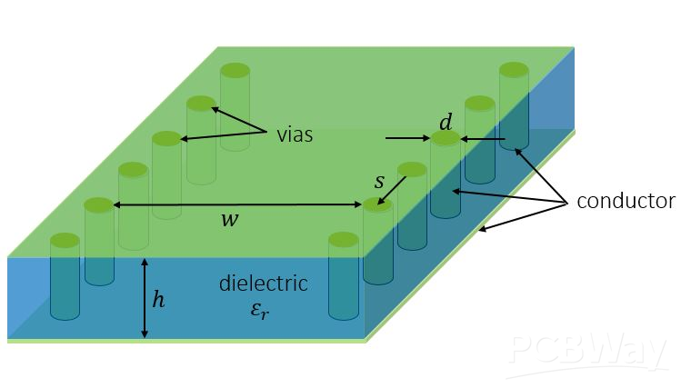
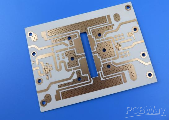
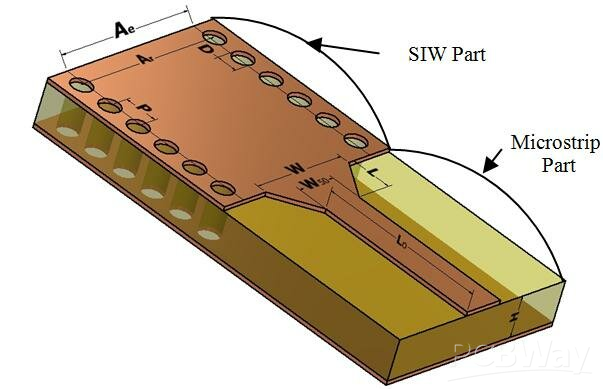
This project is about designing and experimentally validating compact SIW microwave components on Rogers RO4003C around 2.47 GHz. The main prototype is an unequal SIW directional coupler that uses via-fence SIW walls and a microstrip-to-SIW transition. Unequal coupling is achieved by a controlled “via perturbation” approach, where selected vias near the coupling region are intentionally displaced to tune the EM field distribution and coupling level.
In parallel, I also developed a three-port SIW power divider using a Y-junction SIW topology and internal via-wall shaping for controlled power splitting.
These PCBs are for academic research only and will be used for simulation verification, SMA soldering, laboratory measurements, and journal publication—no commercial use is intended.
High-frequency SIW prototypes on Rogers material are expensive, and for a student research budget this cost directly limits how many measurement iterations can be done. PCBWay’s support would allow faster and higher-quality fabrication of these microwave boards, enabling me to validate EM simulations with real hardware results, iterate quickly, and strengthen the experimental evidence needed for publication. I’m excited about the opportunity to collaborate with PCBWay and share measurable RF/microwave outcomes with the community—showing how academic electromagnetics research can turn into practical, working hardware.
- Academic Research
- Measurement
- RF PCB
- Microstrip-to-SIW Transition
- Microwave
- 247GHz
- Rogers RO4003C
- Power Divider
- Directional Coupler
- Substrate Integrated Waveguide
- SIW
You might like


- Comments(0)
- Likes(1)
-
-
-
 Gabber Burgundo
-