


Build a Real-time Clock Circuit with a DS1307 Chip
In this project, we are going to build a real-time clock using a DS1307 real-time-clock chip.
We will show how to build a RTC circuit from scratch using the DS1307 chip.
A real-time clock, or RTC, is an integrated circuit that keeps track of current time. It can keep track of all time from the year down to the second. So it's a very versatile chip. And it can keep track of time in either 12-hour or 24-hour format.
RTCs are widely used in many different devices which need accurate time keeping.
Real-time clocks normally have batteries attached to them that have very long life. Therefore, the batteries last a very long time, several years. The battery keeps the RTC operating, even when there is no power to the microcontroller that is connected up to. So even if the microcontroller powers off, the RTC can keep operating due to its battery. Therefore, it can always keep track of the current time and have accurate time, ongoing.
Therefore, learning about them, how to build a RTC circuit from a chip and how to connect it to a microcontroller, and program it is very useful.
Components
- DS1307 real-time clock chip
- Coin Battery Holder
- CR2032 Coin Battery
- 32.768KHz Crystal Oscillator
- 2 1KΩ resistors
- Power Source
The DS1307 is a real-time clock chip which can count seconds, minutes, hours, date of the month, month, day of the week, and year with leap-year compensation.
It's a great clock that can always keep track of time regardless of whether the microcontroller it connects to is powered on or off. This means if you shut off the microcontroller, the chip will still keep track of time ongoing. A microcontroller, on the other hand, without a real-time clock chip, will restart time to back to the beginning 0 everything it's powered off. With RTCs, with critical or time-sensitive applications, we can always keep a precise record of time.
The DS307 is an 8-pin chip.
The pinout of the DS1307 is shown below.

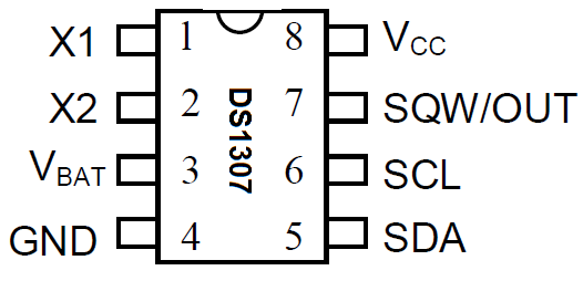
The DS1307 needs a crystal oscillator in order to work. It operates on a 32.768 oscillator. So we connect this oscillator to pins 1 and 2.
Pin 3 connects the battery's power supply. The DS1307 works well with a CR2032 coin battery. This battery functions as the backup power source for the chip when not powered by an external source.
Pin 4 serves as ground (GND).
Pin 5 is the serial data line (SCL). It's the line that transmits the time from the RTC chip to the microcontroller it's connected to.
Pin 6 is the serial clock line (SCL). The serial clock line is needed to synchronized data movement on the serial interface.
Pin 7 is the square wave/output driver (SQW). This allows us to change the square wave frequencies to either (1Hz, 4KHz, 8KHz, or 32KHz). For our basic application, we will not be adjusting the square wave frequency, so we leave the pin unconnected.
Pin 8 is the positive power voltage supply (VCC). VCC should be about 5V. When VCC is supplied a voltage above the battery's voltage, the chip will function off of VCC. The battery is only used when VCC falls below Vbat.
DS1307 Real-time Clock Circuit
The real-time clock circuit we will build with a DS1307 is shown below.
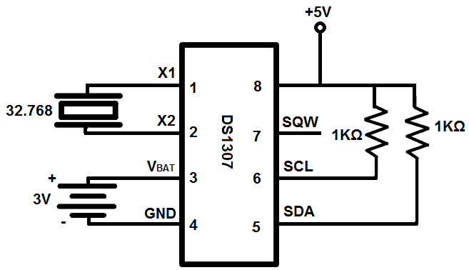
So we connect the 32.768KHz crystal oscillator to pins 1 and 2 on the DS1307.
We connect positive and negative terminals of the 3V battery to pins 3 and 4, respectively.
Both SDA and SCL, pins 5 and 6, require an external pull-up resistor connected to VCC. This is because inside the chip are transistors that are open drain. In order to complete the transistor circuit, positive voltage needs to be applied to the drain. Then the transistor can conduct current across from drain to source.
Pin 7, we leave unconnected.
And pin 8 gets attached to an external power source of 5V approximately.
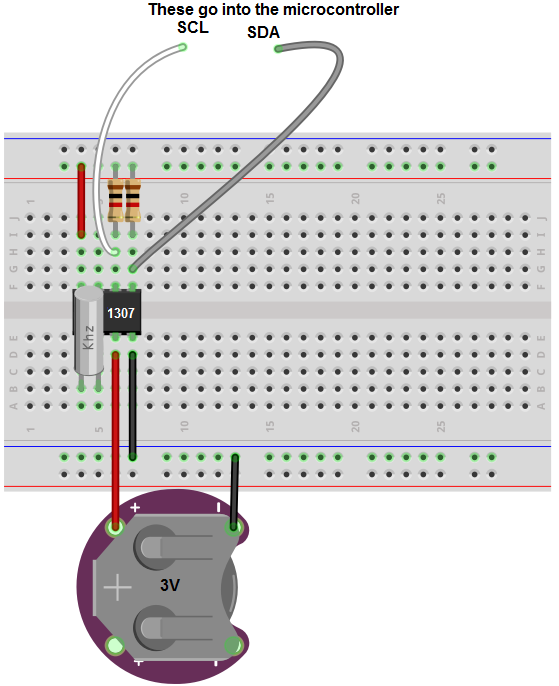
Once this is done, we've completed our circuit. Now the only 2 pins that need to be connected to a microcontroller are SDA and SCL, pins 5 and 6. These need to be connected to analog pins of a microcontroller. Then with the right code, this circuit can always keep track of time.
And this is how we can build a real-time clock circuit with a DS1307 RTC chip.
- PCBWAY
- DS1307
- rduino
You might like


- Comments(0)
- Likes(0)