


MechaSlam Rocket Precision Landing Flight Computer
The MechaSlam rocket flight computer is an innovative PCB that runs Guidance Navigation and Control (GNC) onboard my latest TVC rocket- ZeroLock. The aim of this rocket is to achieve a soft landing - but not just anywhere. Precision landing on the launch tower is the ultimate goal, inspired by SpaceX's Falcon 9 heavy.
This is an early-stage, custom-designed flight computer developed to build a vertically landing model rocket. This board implements basic PID control with real-time sensor data and is designed for thrust vectoring actuation for stable flight. It represents the first phase of a long-term R&D effort toward a full precision-guided reusable rocket system, inspired by Falcon 9 but scaled for educational access.
The next stages will integrate computer vision, and nonlinear model predictive control (NMPC), all handled onboard- something never seen before at an amateur rocketry scale. Future versions will use a 4-layer high-density SMD PCB rather than a simple 2 layer board design this initial prototype validates the core control loop and hardware integration.
1. Power Delivery Unit
The PCB includes onboard power regulation using multiple LMR16030 buck converters to step down LiPo battery voltage to regulated 5V, 3.3V, 6V and 1.8V rails. These power critical subsystems like the STM32 microcontroller, Raspberry Pi CM4 and Zero 2, servos, and sensors. Decoupling capacitors and ferrite beads are used for noise suppression. High-current traces are routed with thick polygons and thermal reliefs. Test points are provided for live debugging.
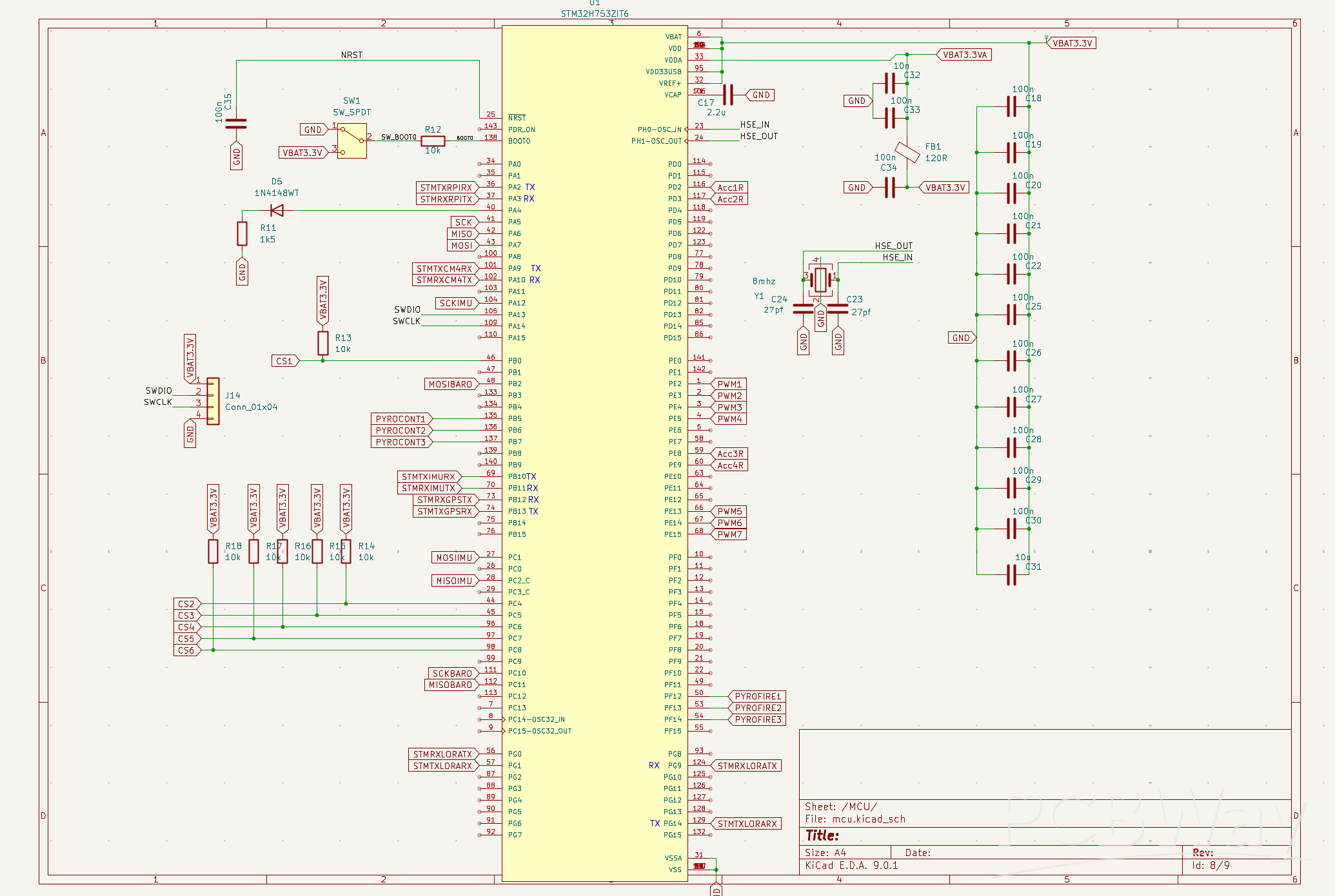
2. Main Flight Control Unit (MCU Core)
The core of the board is an STM32H753ZIT6, a 400MHz high-performance ARM Cortex-M7 MCU, used for real-time flight control tasks including Thrust Vector Control (TVC), fin guidance, and sensor fusion. It features:
Dual SPI buses with dedicated chip-select lines for time-synchronized sensor reads
SD card logging via SDIO
Hardware timers for precise PWM signal generation to 6 servos (TVC and airbrake actuators)
Built-in watchdogs and brownout detection for robustness
3. Inertial and Environmental Sensing Suite
A dual-IMU setup is used for high-reliability inertial measurement:
BNO085 (sensor fusion with 9-axis output)
ICM-42688-P (high-performance raw gyro/accel)
These are complemented by a BMP390L barometric pressure sensor for altitude data. Redundant I²C and SPI buses are used for sensor isolation and fault tolerance.
4. Proximity and Terrain Awareness
The PCB integrates four Acconeer A121 pulse radar sensors over two SPI buses. These enable high-resolution proximity sensing for vertical terrain mapping during landing phases, assisting the vision system and airbrake deployment. Mounting holes are positioned for angled placement on the rocket body.
5. Compute Vision Subsystems
Two Raspberry Pi modules are integrated:
CM4 for running a nonlinear model predictive controller (NMPC) in real-time
Zero 2 W for handling stereo vision and ArUco tag detection for precision landing
The board includes two camera FFC connectors and USB data lines routed for video input. A third camera can optionally be mounted for dedicated ArUco tag tracking or obstacle detection.
6. Wireless Communication
The PCB includes footprints and level-shifted UART/SPI connections for:
LoRa module (900 MHz telemetry to ground station)
Bluetooth module (for pre-launch app-based control and status updates)
Antennas are routed with controlled-impedance lines and matched with 50-ohm trace widths.
7. Debugging & Expandability
Multiple test points for SDA, SCL, 5V, GND, and UART lines
JTAG/SWD port for flashing and debugging the STM32
Breakout headers for future additions (GNSS, pyro channels, CAN bus)
2.54mm pin pads for servo connections (direct solder or JST)
8. Mechanical & Thermal Design
4-layer PCB with separate analog and digital ground planes
Two mounting holes for structural integration inside a 74mm diameter rocket airframe
Strategic component placement to reduce EMI and thermal coupling
My team would greatly appreciate the support of PCB in sponsoring this project. As we aim to build more complex and powerful avionics systems, the price increases and sourcing parts becomes difficult. Futhermore, PCBWay's reliable and extensive PCB manufacturing capabilities would result in a final product that would be extremely high quality and capable. We have prototyped a v1 of this flight computer (shown below), however it is incapable of running non linear model predictive control due to the lack of computing power onboard. With PCBWay's support, we hope to reach new heights in the field of amateur thrust vector control rockets.
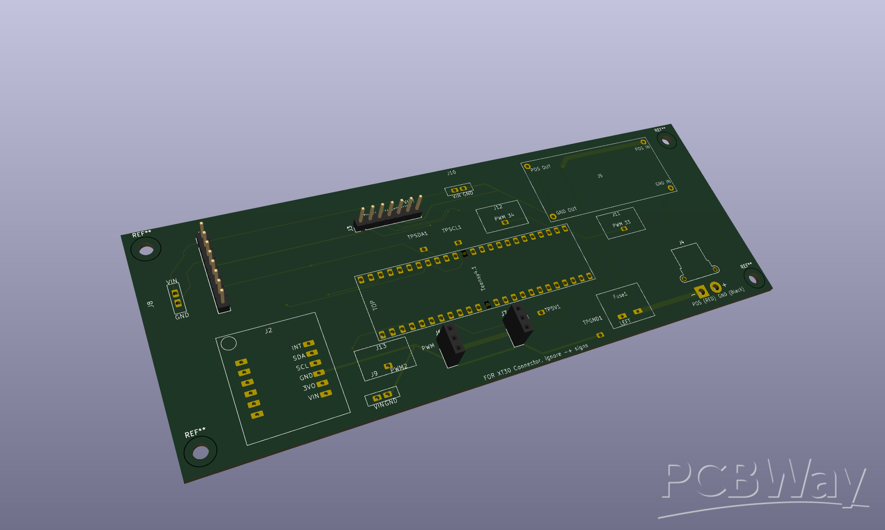
Picture Above: Prototype v1
Picture above: Final Board v2 (In progress)
- thrust vector control
- tvc
- pcb
- cm4
- amateur
- model rocketry
- flight computer
- rocket
- fc
You might like


- Comments(1)
- Likes(1)
-
-
 Engineer
 Oct 17,2025
hey, did you finish designing this?
-
-
-
Engineer
-