


DIY Idea with RFID
Hello Friends, in this video i will show you How to Make a Rfid Door Lock with led On
. im using the Arduino uno and Rfid for Making it. its very portable and very easy to make.
Things That i used:
Arduino uno :
Rfid:
Servo Motor :
Relay:
Jumper wire :
Led:
Arduino cable:
Hardware Overview – RC522 RFID Reader/Writer Module:-
What is an RFID reader?
RFID tagging is an ID system that uses small radio frequency identification devices for identification and tracking purposes. An RFID tagging system includes the tag itself, a read/write device, and a host system application for data collection, processing, and transmission.
In simple words an RFID uses electromagnetic fields to transfer data over short distances. RFID is useful to identify people, to make transactions, etc…
You can use an RFID system to open a door. For example, only the person with the right information on his card is allowed to enter. An RFID system uses:
>> tags attached to the object to be identified, in this example we have a keychain and an electromagnetic card. Each tag has his own identification (UID).
>> The MFRC522 RFID module based on MFRC522 IC from NXP is one of the most inexpensive RFID options that you can get online for less than four dollars. It usually comes with a RFID card tag and key fob tag having 1KB memory. And best of all, it can write a tag, so you can store your some sort of secret message in it.
The RC522 RFID module based on MFRC522 IC from NXP is one of the most inexpensive RFID options that you can get online for less than four dollars. It usually comes with a RFID card tag and key fob tag having 1KB memory. And best of all, it can write a tag, so you can store your some sort of secret message in it.The RC522 RFID module based on MFRC522 IC from NXP is one of the most inexpensive RFID options that you can get online for less than four dollars. It usually comes with a RFID card tag and key fob tag having 1KB memory. And best of all, it can write a tag, so you can store your some sort of secret message in it.
A Reader consists of a Radio Frequency module and an antenna which generates high frequency electromagnetic field. On the other hand, the tag is usually a passive device, meaning it doesn’t contain a battery. Instead it contains a microchip that stores and processes information, and an antenna to receive and transmit a signal
To read the information encoded on a tag, it is placed in close proximity to the Reader (does not need to be within direct line-of-sight of the reader). A Reader generates an electromagnetic field which causes electrons to move through the tag’s antenna and subsequently power the chip.
In the piece of code above you need to change the if (content.substring(1) == “REPLACE WITH YOUR UID”) and type the UID card you’ve written previously.
Basic Specifications:
- Input voltage: 3.3V
- Frequency: 13.56MHz
After doing so, restart your ArduinoIDE.
Now, our Arduino is ready to take commands and execute accordingly.
The Arduino Code has been uploaded at the end of this tutorial. Compile the code and eliminate "typo" errors (if any).
Now, its time to connect our Arduino with the RFID reader. Refer to the PIN wiring below,as well as the Connection schematic diagram for easy reference.
PinWiring to Arduino Uno
SDA------------------------Digital 10
SCK------------------------Digital 13
MOSI----------------------Digital 11
MISO----------------------Digital 12
IRQ------------------------unconnected
GND-----------------------GND
RST------------------------Digital 9
3.3V------------------------3.3V (DO NOT CONNECT TO 5V)
Reading data from an RFID tag
After having the circuit ready, go to File > Examples > MFRC522 > DumpInfo and upload the code. This code will be available in Arduino IDE (after installing the RFID library).
Then, open the serial monitor. You should see something like the figure below:
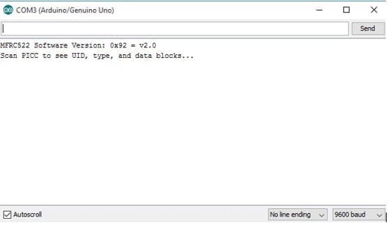
Approximate the RFID card or the keychain to the reader. Let the reader and the tag closer until all the information is displayed.
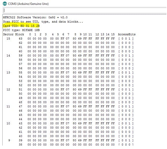
This is the information that you can read from the card, including the card UID that is highlighted in yellow. The information is stored in the memory that is divided into segments and blocks as you can see in the previous picture.
You have 1024 bytes of data storage divided into 16 sectors and each sector is protected by two different keys, A and B.
Write down your UID card because you’ll need it later.
Upload the Arduino code that has been suffixed here.
Demonstration
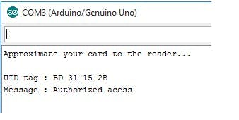
Approximate the card you’ve chosen to give access and you’ll see:
caption (optional)
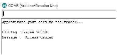
If you approximate another tag with another UID, the denial message will show up:
In case of any queries please comment below.
#include <SPI.h>
#include <MFRC522.h>
#define RELAY 8
#define SS_PIN 10
#define RST_PIN 9
MFRC522 mfrc522(SS_PIN, RST_PIN);   // Create MFRC522 instance.
void setup()
{
pinMode (RELAY,OUTPUT);
Serial.begin(9600);   // Initiate a serial communication
SPI.begin();      // Initiate  SPI bus
mfrc522.PCD_Init();   // Initiate MFRC522
Serial.println("Approximate your card to the reader...");
Serial.println();
}
void loop()
{
// Look for new cards
if ( ! mfrc522.PICC_IsNewCardPresent())
{
return;
}
// Select one of the cards
if ( ! mfrc522.PICC_ReadCardSerial())
{
return;
}
//Show UID on serial monitor
Serial.print("UID tag :");
String content= "";
byte letter;
for (byte i = 0; i < mfrc522.uid.size; i++)
{
Serial.print(mfrc522.uid.uidByte[i] < 0x10 ? " 0" : " ");
Serial.print(mfrc522.uid.uidByte[i], HEX);
content.concat(String(mfrc522.uid.uidByte[i] < 0x10 ? " 0" : " "));
content.concat(String(mfrc522.uid.uidByte[i], HEX));
}
Serial.println();
Serial.print("Message : ");
Serial.print("RELAY: ");
content.toUpperCase();
if (content.substring(1) == "89 18 79 63") //change here the UID of the card/cards that you want to give access
{
Serial.println("Authorized access");
Serial.println();
Serial.println("Relay on");
digitalWrite (RELAY,LOW);
delay(1000);
}
else   {
Serial.println(" Access denied");
Serial.println(" RELAY off");
Serial.println(" SmartTonics");
digitalWrite(RELAY,HIGH);
}
Rfid Reader circuit


Complete
Thanks Pcbway for your Supporting
- Rfid lock
- Rfid
You might like


- Comments(0)
- Likes(0)