

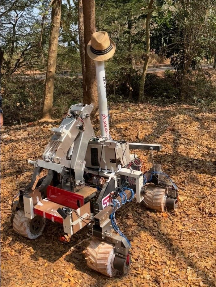
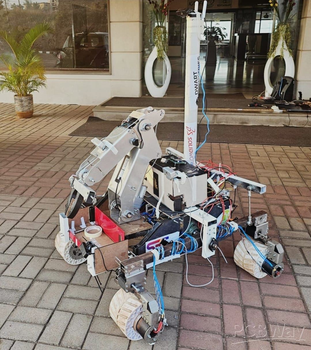
Autonomous Martian Rover - CRISS Robotics
We are CRISS Robotics, the leading space engineering & robotics society of BITS Pilani, Pilani Campus, India, an institute of eminence recognized by the Government of India. We are a team of 40+ motivated students setup in 2021, working beyond deadlines, making rovers & drones for advancements in science & technology, with a keen focus on sustainability, authenticity, and low carbon emissions.
We have a brilliant track record in space engineering competitions, including:
- Internationally 3rd in the European Rover Challenge 2025
- 3x award winners in International Rover Design Challenge (2022,2023,2024)
- 2nd Place across the Globe: European Rover Challenge 2022
- Top 10 finishes in International Rover Challenge and International Mars Base Challenge (2022,2023,2024)
- Finalists of RoboFest, organized by the Gujarat Council on Science and Technology (2024)
Find more about us at: https://www.criss-robotics.in/
CRISS Robotics employs a tailored, rigorous V-model systems engineering lifecycle, emphasizing concurrent engineering between hardware and software teams, with a timeline culminating in March 2026. This ensures design maturity is appropriate to proceed with full-scale fabrication and testing. The project is organized into five specialized, highly integrated subsystems: Mechanical, Electrical, Payload & Experimentation, Software, and Management.The development is divided into four main phases:
- Phase A (Requirements & Concept - March to April 2025): High-level mission goals were decomposed into over 100 functional and non-functional requirements. Initial trade studies were performed.
- Phase B (Preliminary Design & Prototyping - June to August 2025): Subsystem PDRs (Preliminary Design Reviews) were conducted. Key mobility, manipulation, and communication prototypes were validated.
- Phase C (Final Design & CDR - September to October 2025): Final component selection and architecture lock-down, including the integration of major enhancements: NVIDIA Jetson Orin Nano and Pivot Steering. This CDR marks the conclusion of this phase.
- Phase D (Fabrication, Assembly, and Integrated Testing - November 2025 to March 2026): The current and most critical phase, involving full-scale manufacturing, stackable PCB fabrication, detailed sub-system integration, and comprehensive system-level testing (IST) leading up to the competition.
The core of our approach is ensuring that every subsystem works together, with frequent bi-weekly meetings of the Executive Committee consisting of the Team Captain and the individual Subsystem Lead & Vice-Lead. These individuals along with a rigorously recruited group of juniors act as cross-disciplinary liaisons, tasked with managing the technical interfaces between multiple subsystems like the Stackable PCB Electrical Box and the Software Subsystem (Jetson Orin Nano), mitigating integration risks and accelerating the final assembly schedule along with efficient team management.
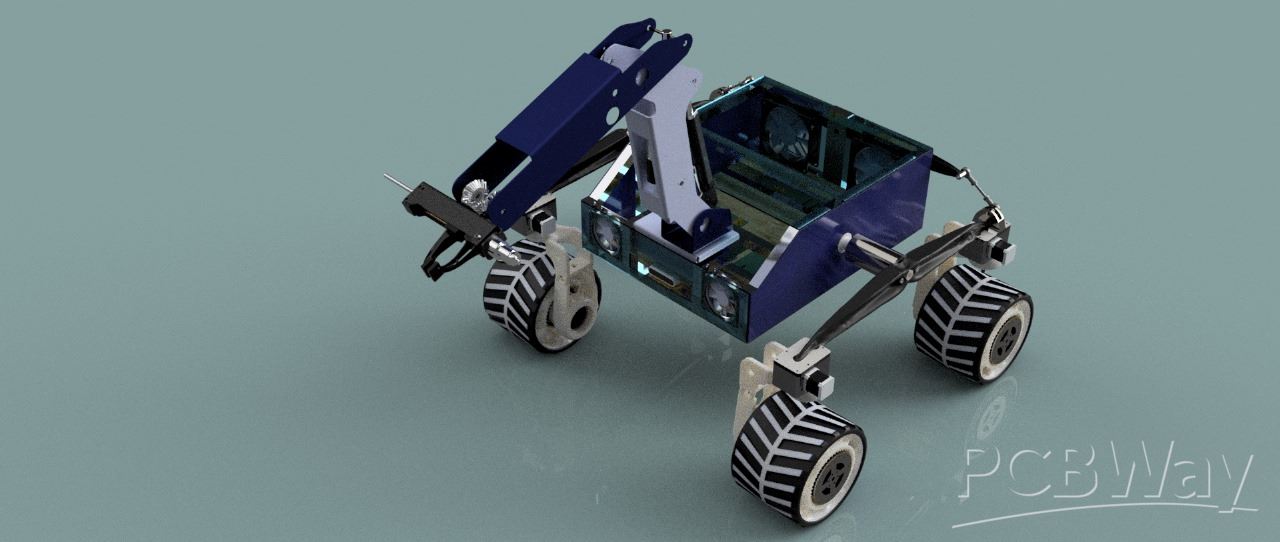
Everything on the rover is custom designed ourselves. A structured solution-space exploration guided each subsystem’s design, following industry-standard trade-off analysis for redundancy, efficiency, and performance.
- Mobility Architecture: Skid steering was rejected due to high power loss, tire wear, and odometry errors. Pivot steering was selected for four-wheel control, minimal slip, improved energy efficiency, and precise odometry—critical for mapping and navigation tasks.
- Computational Platform: A standard SBC lacked the processing power for real-time ML and multi-camera handling. The NVIDIA Jetson Orin Nano was chosen for its GPU acceleration, enabling real-time terrain classification and intelligent path planning.
- Communication System: The single-band 2.4 GHz setup limited data throughput. The Mikrotik Metal 52 dual-band antenna enables 5 GHz high-speed data transfer for visuals and spectroscopy while retaining 2.4 GHz for long-range failsafe control.
- Payload Integration: An onboard NIR spectroscope enables advanced mineralogical analysis, supported by a sample caching and sealing mechanism to prevent contamination and preserve scientific integrity.
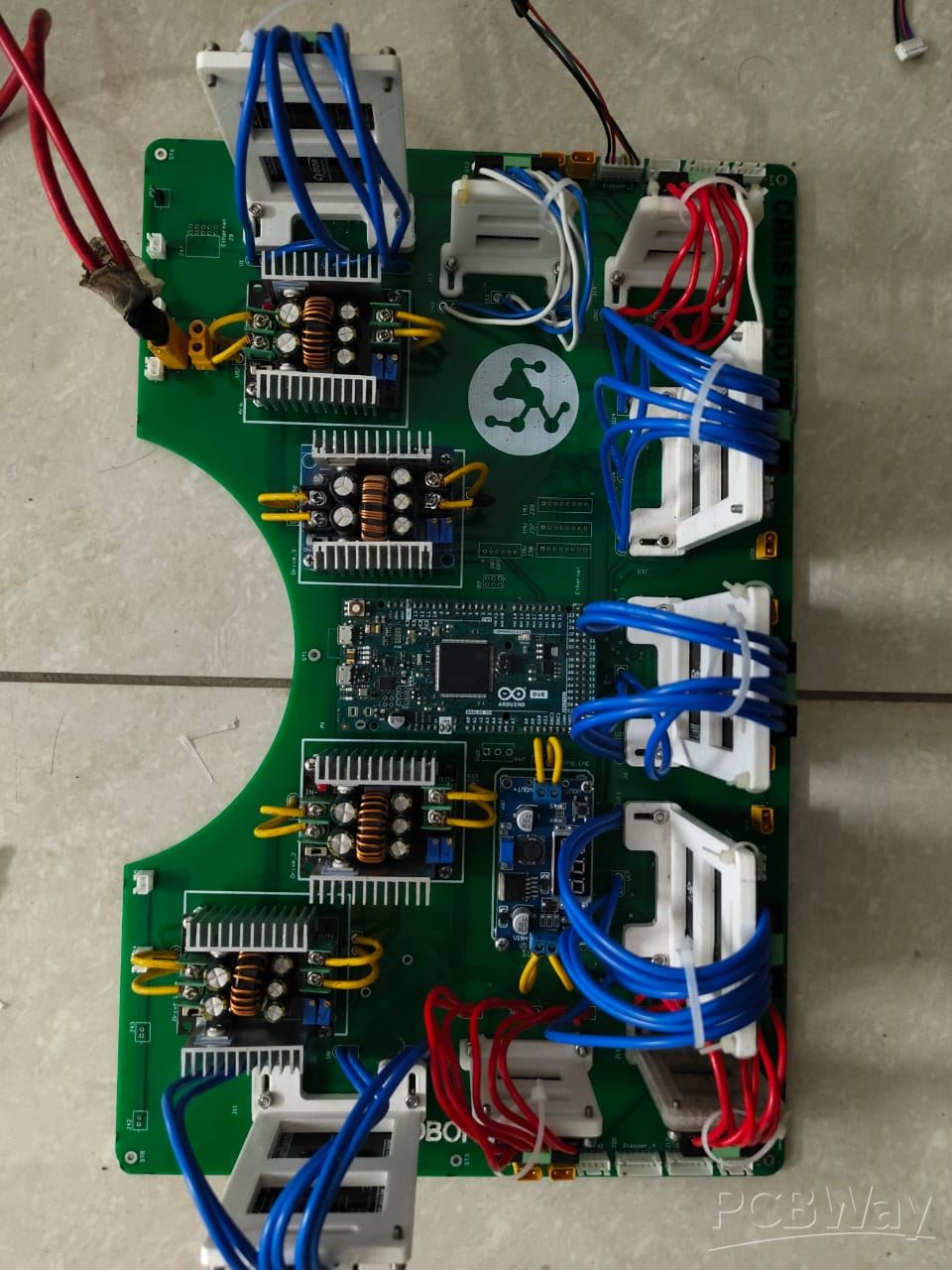
An Arduino Due along with an ESP32 are used to control a rover’s drive system. Four planetary geared DC motors equipped with Hall effect sensors for accurate speed and position feedback control the main motion. This arrangement allows the rover to achieve smooth acceleration and precise speed control. Additionally, the rover features a pivot steering mechanism driven by 4 NEMA-17 stepper motors, which provide high positional accuracy and controlled maneuverability. Limit switches have been installed at the end of each pivot to prevent over rotation. They work by detecting when a motor hits the limits and sends a feedback signal to the MCU to stop motor rotation. All motors are managed by MDD10A dual-channelled DC motor drivers.
The Battery Management system provides Power to the whole rover, providing three voltage lines - 3.3V, 5V and 12V. Buck converters are used to step down voltage to achieve required voltages from 12.8V. The choice of using buck converters was made owing to their high efficiency, compact and lightweight form factor paired with minimal thermal dissipation. 20A bucks are being used to power the drive train, internal arm motors and NEMA 34 for arm base. The 3A Bucks are used to power the encoders. The 3.3V lines are used to power a LoRa Module (Long Range Communication Module) and an ESP32. The 5V lines power ADS1115 ICs. The ADS1115 IC is used to convert Analog Voltage to Digital Signals that can be communicated over I2C-protocol, and using them with voltage dividers allows us to get 16-bit precision with low noise. It is used to measure differential voltage with respect to a common ground, and is employed in our PCB to measure and keep track of the cell voltages used in the battery pack. It is also used to measure the current drawn from the battery using a small 2 milli-Ohm shunt resistor. The ADS1115 ICs are controlled by the ESP32, which handles calculations to obtain actual voltages and currents to ensure safe levels of current flow through the lines. The ESP32 is also responsible for relaying the voltage and current measurements to the base station through the LoRa module. The 12V lines are used to power 8 fans to maintain optimal temperature inside the rover for smooth functioning. The rover uses a Lithium Ferric Phosphate battery with a substantial capacity of 24Ah and voltage of 12.8V. A provision to cut off power swiftly during emergencies has been done through fuses to account for errors and disruptions.
This is the drive link containing our recent work images and videos: https://drive.google.com/drive/folders/1rwYCovLG8z3tm31wQYRGuOlUSpua6L4H?usp=sharing
- Custom Design
- Autonomous
- Robotics
- Martian Rover
You might like


- Comments(0)
- Likes(1)
-
-
-
 CRISS Robotics
-